Introduction
You know that feeling? It’s 11 PM, you’re rebooting your Proxmox server to check that the new configuration works correctly, and then… disaster. SSH access is gone, the web interface no longer responds, and of course your server is tucked away in a corner of the room with zero desire to drag out a monitor and keyboard to debug it physically.
That’s where PiKVM comes in. This open source project turns a simple Raspberry Pi into a KVM over IP. You get BIOS and terminal access as if you were sitting in front of the machine, all through a web browser.
In this article, I’ll walk through how I set up PiKVM v2 (the latest DIY version) on a Raspberry Pi Zero 2 W. It’s compact, it’s effective, and it’ll save me the next time my server crashes on reboot. No more moving a monitor, keyboard, and mouse. I’ll just access my server from my browser. Let’s get started with the tutorial!
1. KVM, What Is It?
Behind this acronym (Keyboard Video Mouse) lies a vital tool: a switch that lets you control multiple computers from a single keyboard/monitor/mouse setup. PiKVM goes further by sending these signals over the network (IP), hence the term KVM over IP.
In practice, your Raspberry Pi “captures” the HDMI video stream from the server and emulates a USB keyboard/mouse. Unlike classic remote access (SSH, RDP, VNC), PiKVM works even when the server’s operating system is crashed or in the middle of a BIOS boot.
All-in-one solutions exist, but I preferred to build my own KVM. I like tinkering and getting my hands dirty, and I have a clear preference for open source, affordable tools that I’ve assembled myself. PiKVM checks all those boxes, including one that was essential for me: Wi-Fi, because my server’s location doesn’t allow me to plug the KVM in via Ethernet (unless I run a 15-meter cable through my entire living room!).
2. The Shopping List
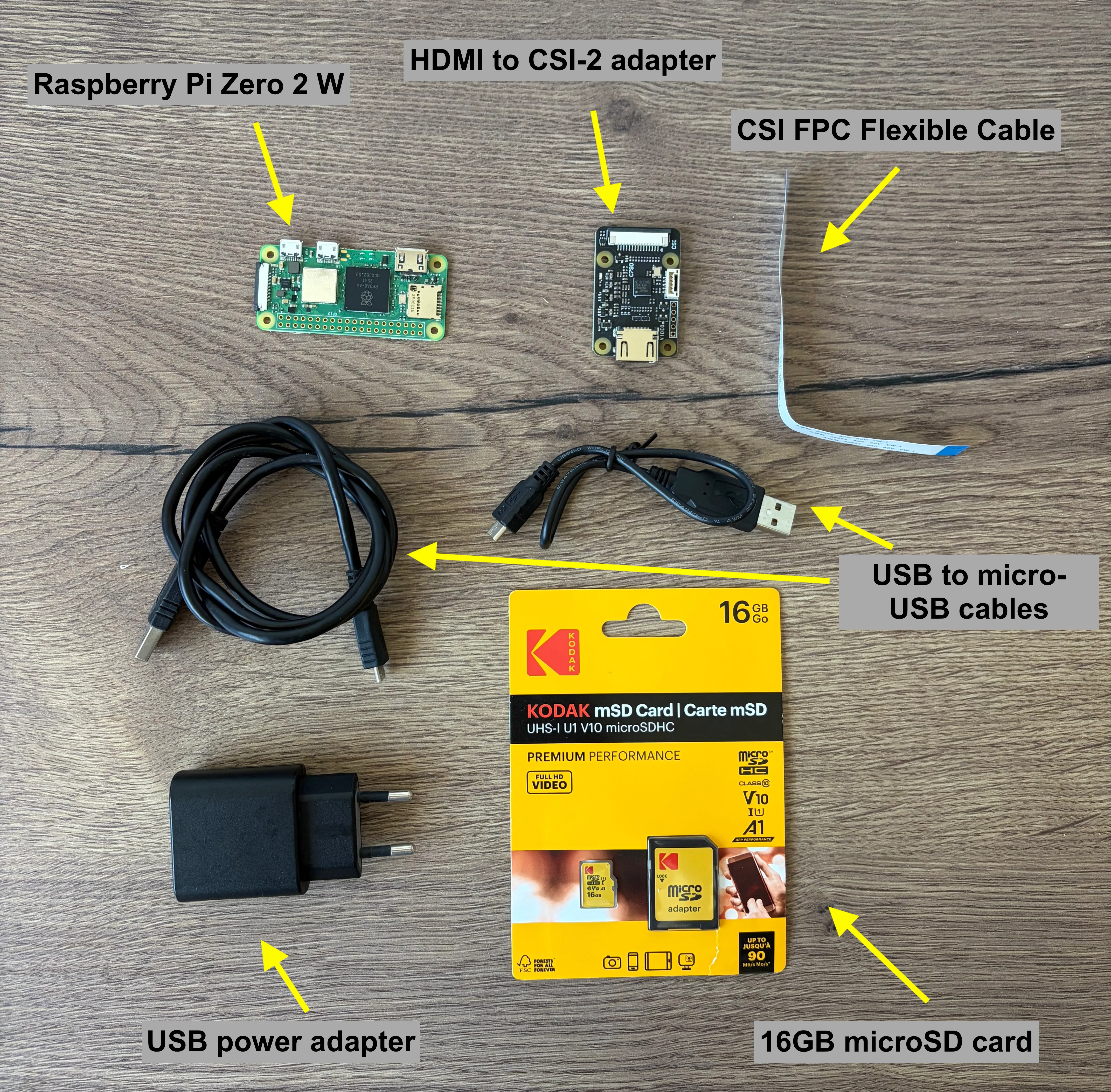
To build a DIY PiKVM, here’s what you need:
- A Raspberry Pi Zero 2 W
- A class 10 microSD card with at least 16 GB
- An HDMI to CSI-2 adapter: This small module captures the server’s HDMI video stream and sends it to the Raspberry Pi’s CSI-2 port, since its only mini HDMI port can’t capture a video stream (IN), only output one (OUT).
- A CSI FPC cable: to connect the HDMI adapter to the Raspberry Pi (usually included with the adapter)
- Several cables: one HDMI, one USB-A to micro USB, and one micro-USB for power.
- Raspberry Pi Imager or equivalent to flash the OS onto the microSD card
3. Preparing the SD Card
Let’s start with the OS installation. Don’t look for a standard Raspberry Pi OS image, PiKVM provides a pre-configured Arch Linux image ready to go.
First step: Download the PiKVM image for Raspberry Pi Zero 2 W: Download (Link to all images).
Second step: Flash the OS onto the microSD card using Raspberry Pi Imager (RPi Imager). The PiKVM documentation explains step by step how to do it, but I’ll recap the steps below.
-
Download and install the latest version of RPi Imager
-
Plug your microSD card into your PC. Make sure there’s no important data on the card, as everything will be erased during the PiKVM installation process
-
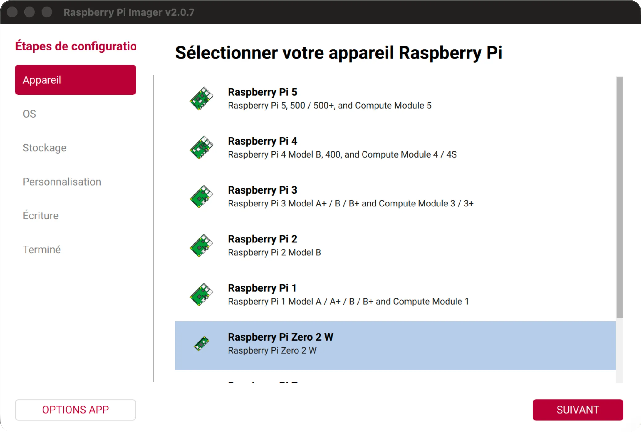
Launch RPi Imager and select your Raspberry Pi device (for me, it’s Raspberry Pi Zero 2 W)
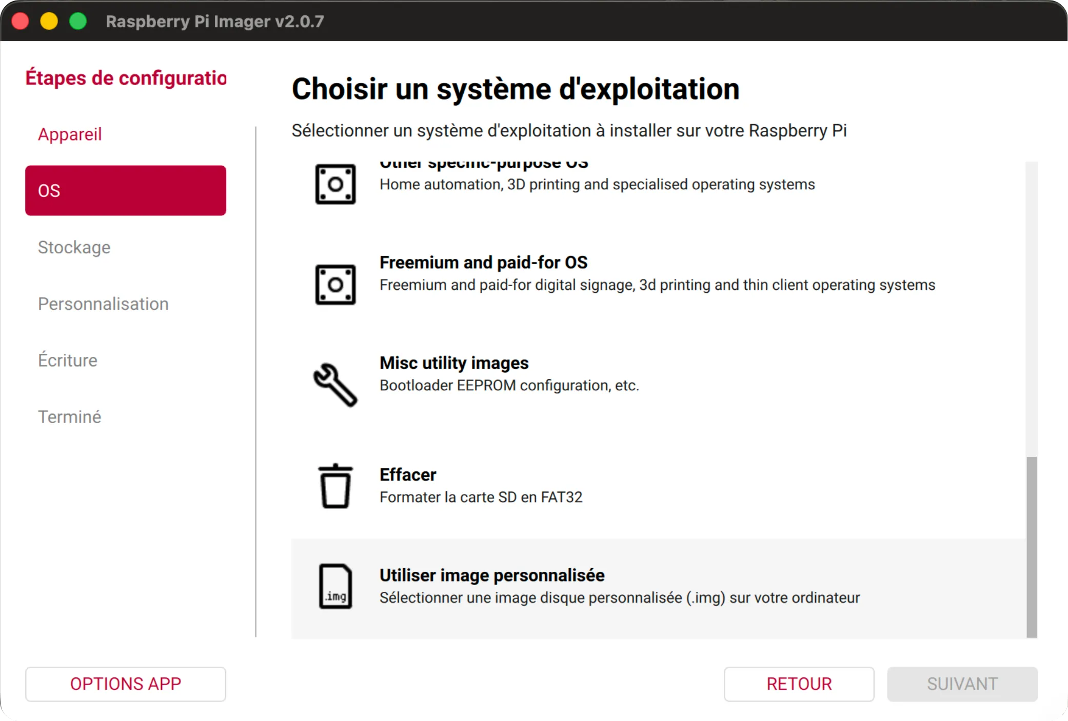
- In the OS section, click “Use custom image” at the bottom of the OS list and select the PiKVM image (
*.imgor*.img.xz) you downloaded in the previous step.
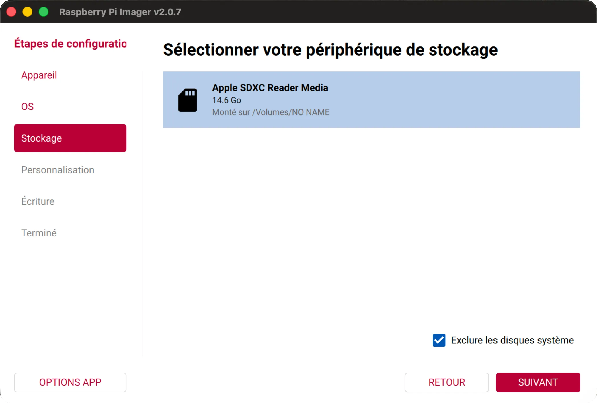
- For storage, select the microSD card where you want to install PiKVM
- Verify everything looks good before writing to the card. If all is well, click “WRITE”
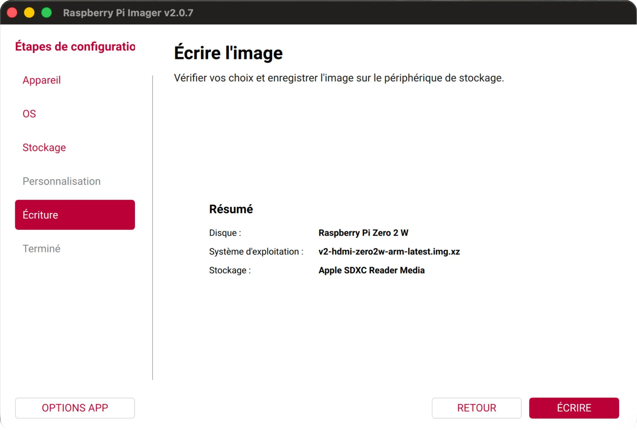
- Confirm the write to the card. Note that, as RPi Imager displays, the process will erase everything on the microSD card with no way to restore it.

- The image is being written to the card. Feel free to grab a coffee/tea and get ready for what’s next.
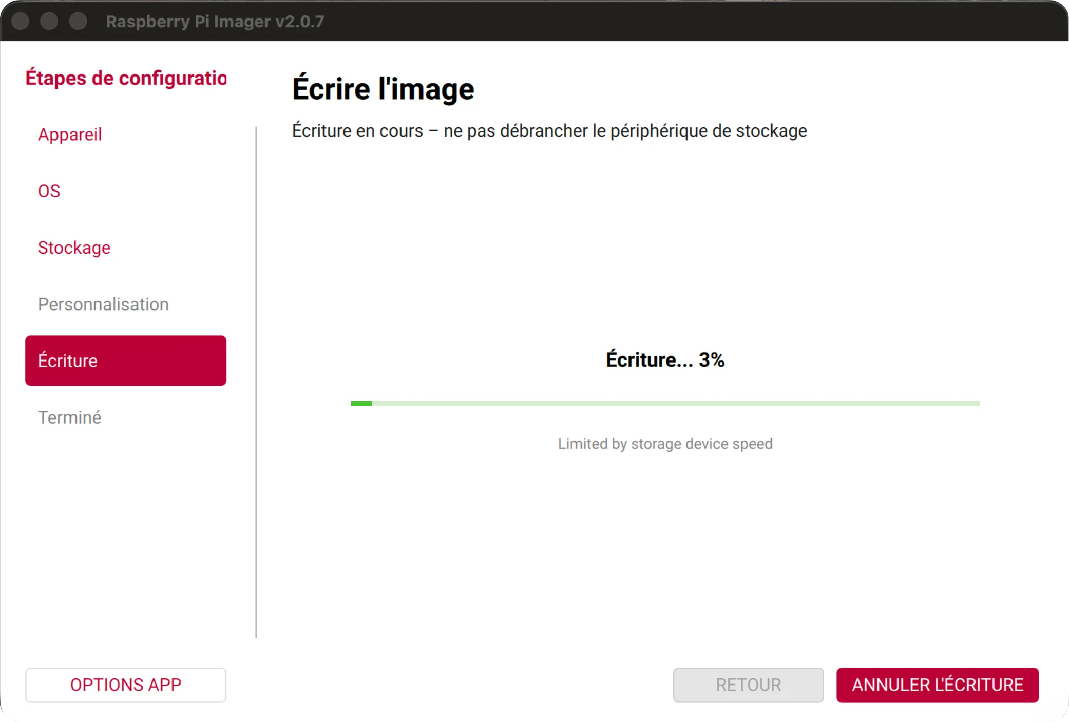
- Once the write is complete, you can remove the microSD card from your PC, as it was automatically ejected by RPi Imager. If there was an error during the write, repeat the process. If it persists, the microSD card may be the issue, so try a different one.

4. Headless Configuration: The pikvm.txt File
This configuration step is crucial, as it lets you configure your PiKVM on first boot (especially Wi-Fi, since the Raspberry Pi Zero 2 W has no Ethernet port and must use Wi-Fi). All settings to apply must be written in a file named pikvm.txt at the root of the SD card. Here are the steps to edit this file following the documentation:
-
Plug the microSD card into your PC and go to the root of the card mount to find the
pikvm.txtfile you’ll need to edit. If PiKVM has never been booted before, the file will only containFIRST_BOOT=1. Do not delete this line. It’s essential for the system to self-install correctly on first boot. -
Edit the following lines to configure your Wi-Fi:
FIRST_BOOT=1  # Do not remove this line
WIFI_ESSID='your_wifi_name'  # SSID (your Wi-Fi network name)
WIFI_PASSWD='your_password'  # Password

# Optional settings
SSH_PORT=54322  # SSH port to connect to PiKVM (22 by default)
WIFI_WPA23=1  # Connect to mixed WPA2/WPA3 networks
WIFI_HIDDEN=1  # Connect to a hidden Wi-Fi network

# To configure a static IP address (DHCP by default):
WIFI_ADDR=192.168.0.100/24  # PiKVM IP address
WIFI_GW=192.168.0.1  # Gateway
WIFI_DNS=8.8.8.8 # DNSImportant: backslashes in the password must be escaped (\\ instead of \)
If you need more options or details, refer to the official PiKVM documentation.
- Save your changes
Once you’ve edited the pikvm.txt file, save your changes, eject the microSD card from your PC, and insert it into the Raspberry Pi Zero 2 W.
Note a few important details:
- the Raspberry Pi Zero 2 W does not support 5 GHz Wi-Fi
- WPA3 is poorly supported, or not supported at all, on the Raspberry Pi Zero 2 W
5. Wiring and First Boot
Wiring
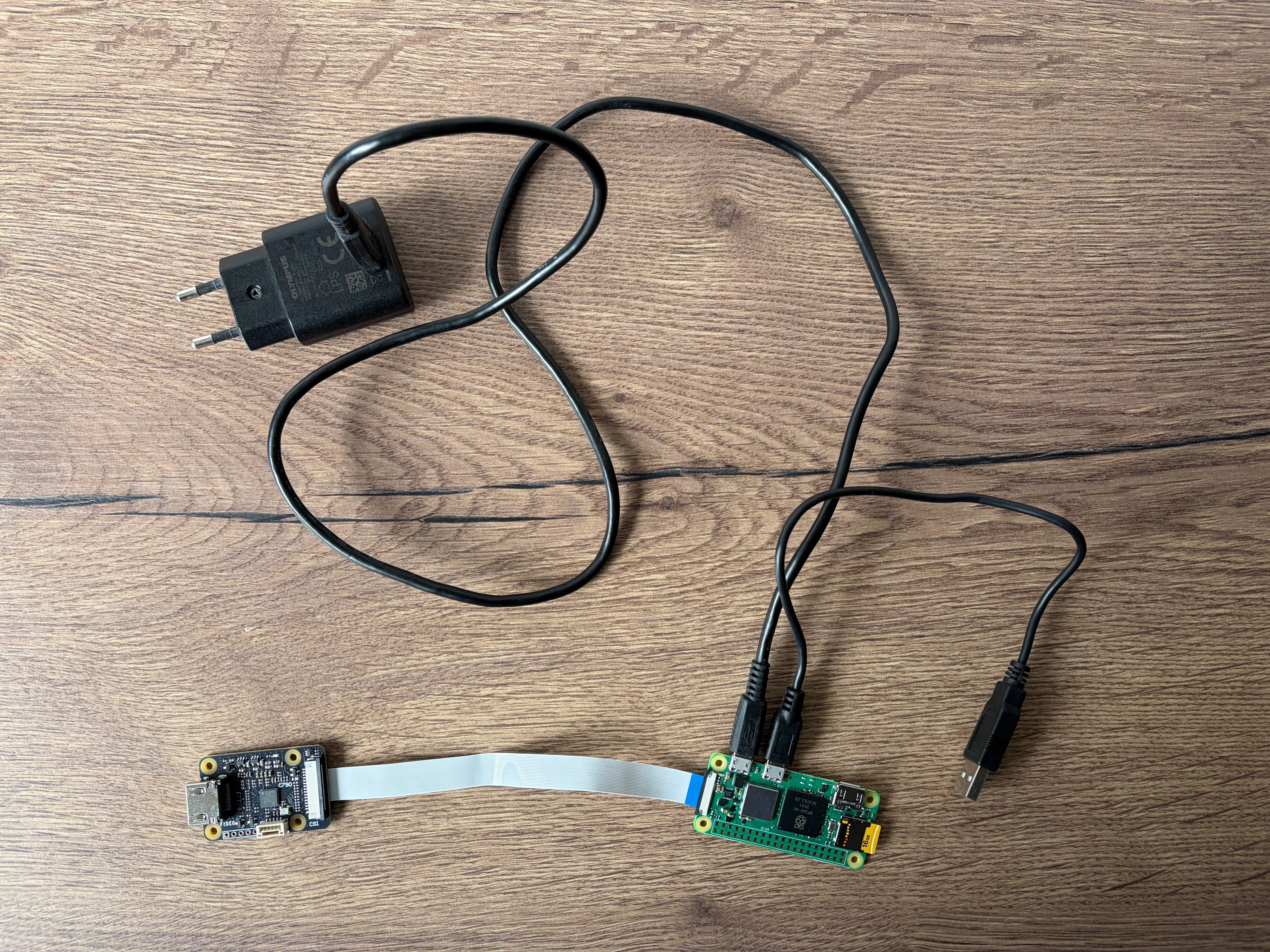
Time to bring this thing to life. Proceed with the connections:
- Connect the CSI FPC cable between the HDMI adapter and the Raspberry Pi.
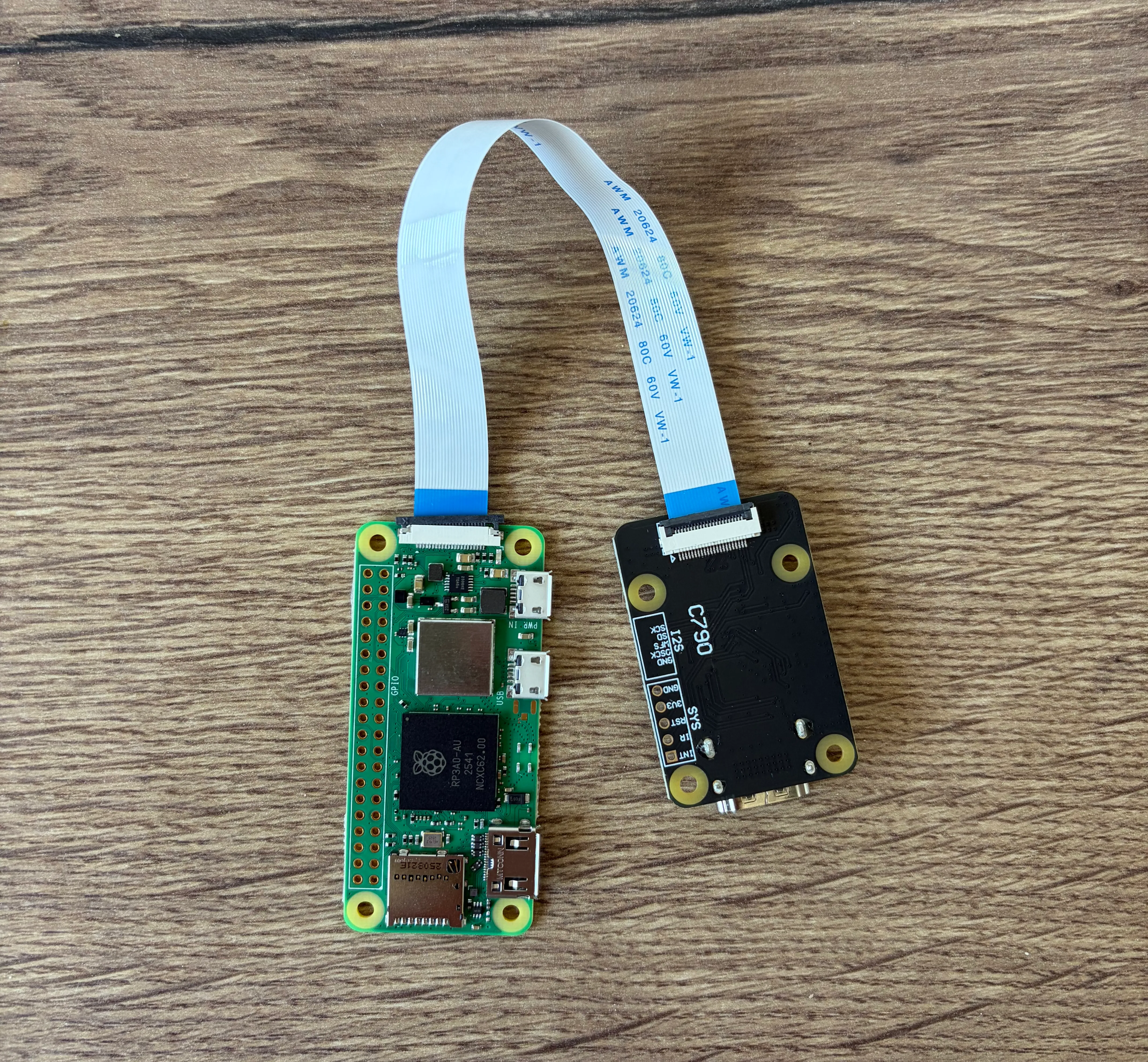
-
Insert the microSD card into the Raspberry Pi
-
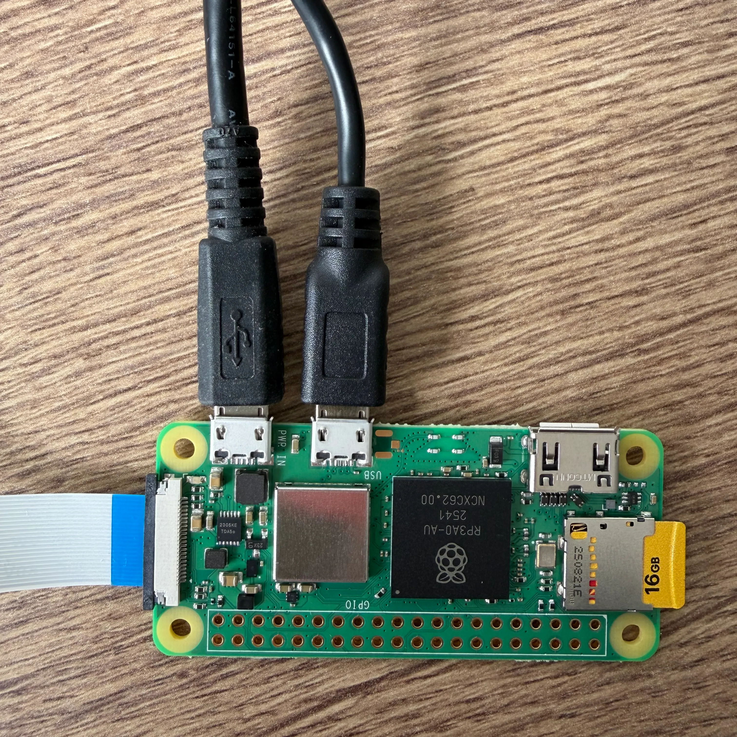
Connect the USB (Data) cable between the Raspberry Pi’s micro-USB port (the one labeled
USB) and a USB port on your server. This cable emulates the keyboard and mouse.
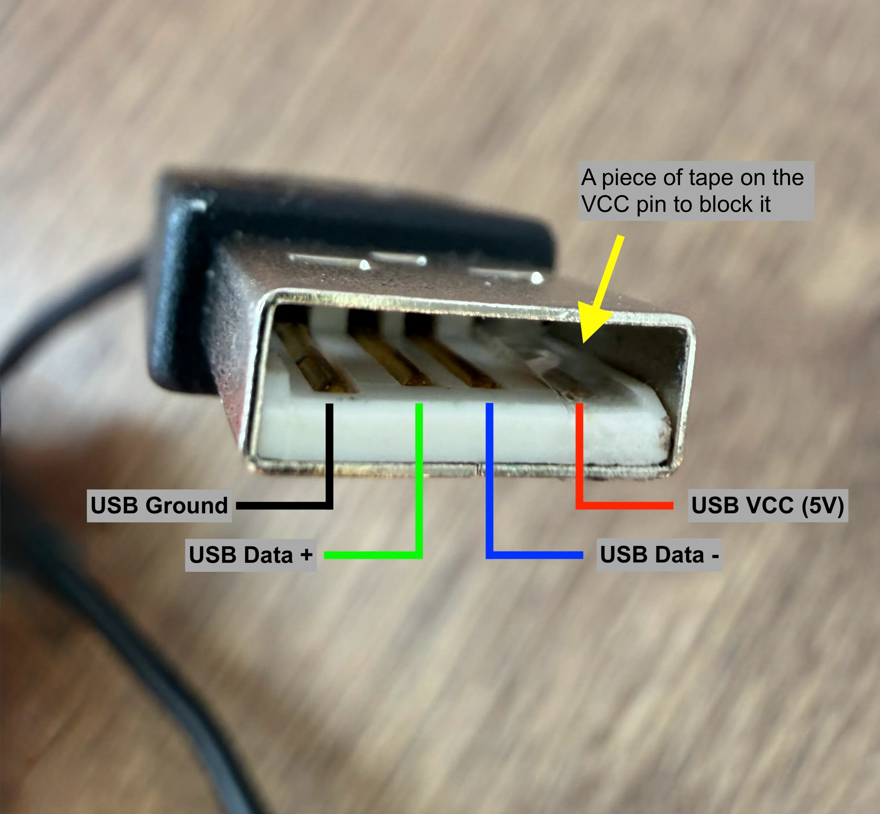
⚠️ Warning! A crucial point before continuing. As the official documentation states, the Raspberry Pi Zero 2 W shares its power line between its two micro-USB ports. If you plug the Pi into wall power AND into the server normally, you’ll inject current into your server’s motherboard (backpowering). This can damage your server.
My DIY workaround: To create a “data-only” cable without cutting anything, I simply placed a tiny piece of tape over the 5V pin (the one on the far right) of the USB-A connector. That way, only data passes through, and my server is protected! To test that it works, I only connected the cable between the micro-USB port labeled USB and my server. If the Raspberry Pi doesn’t power on, it’s working.
- Connect the power cable to the Raspberry Pi’s micro-USB port (the one labeled
PWR IN)
- Finally, connect the HDMI cable between your server and the adapter.
Accessing the Interface
Give PiKVM a few minutes for its first boot. Once ready, find its IP address on your network or use the IP address configured in pikvm.txt and connect via your browser:
https://<YOUR_PI_IP>
Note: if you use a firewall in your setup, make sure the necessary ports are open (HTTP, HTTPS, SSH).
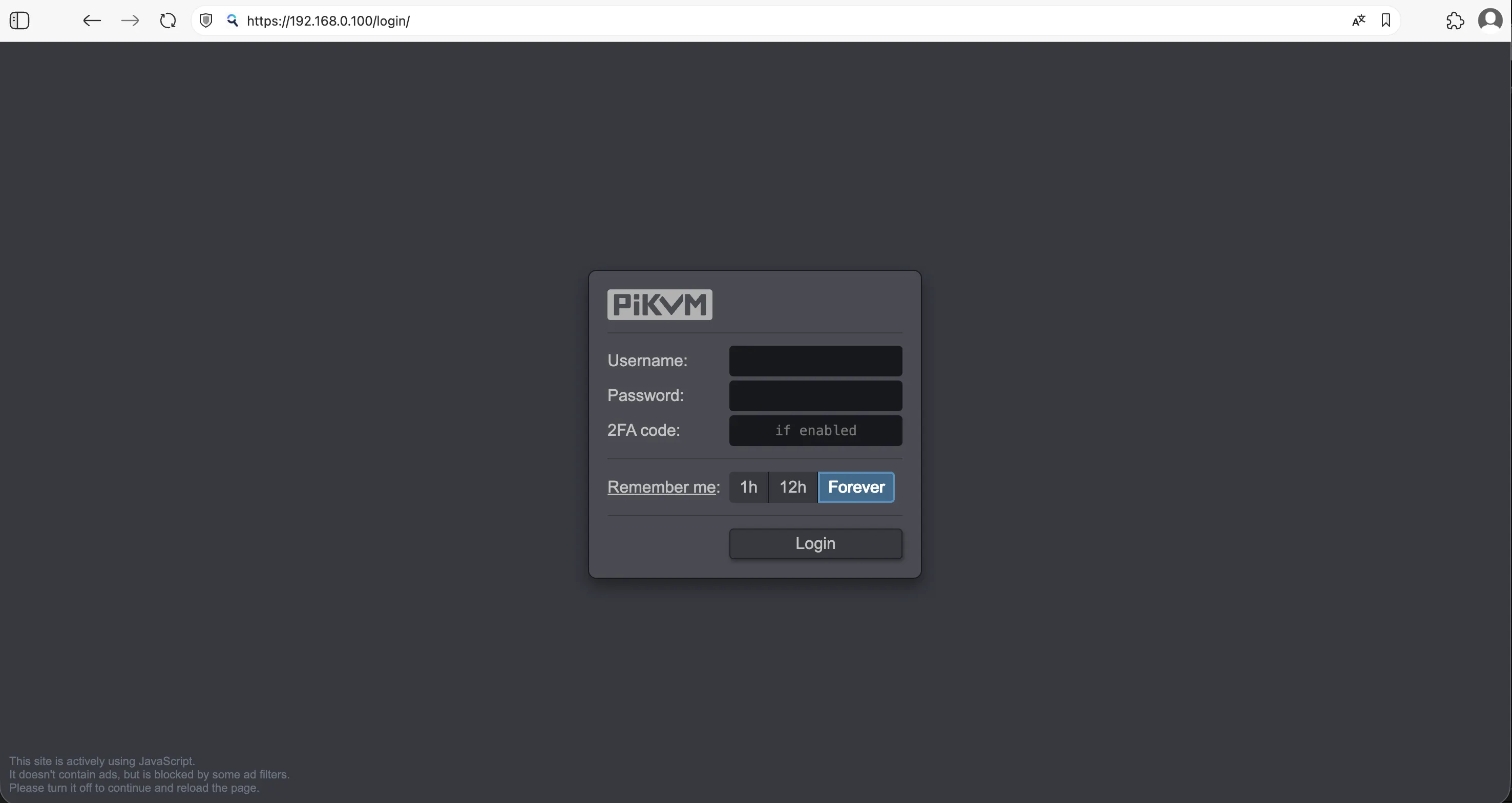
The default credentials are:
- Username:
admin - Password:
admin - 2FA code: disabled by default
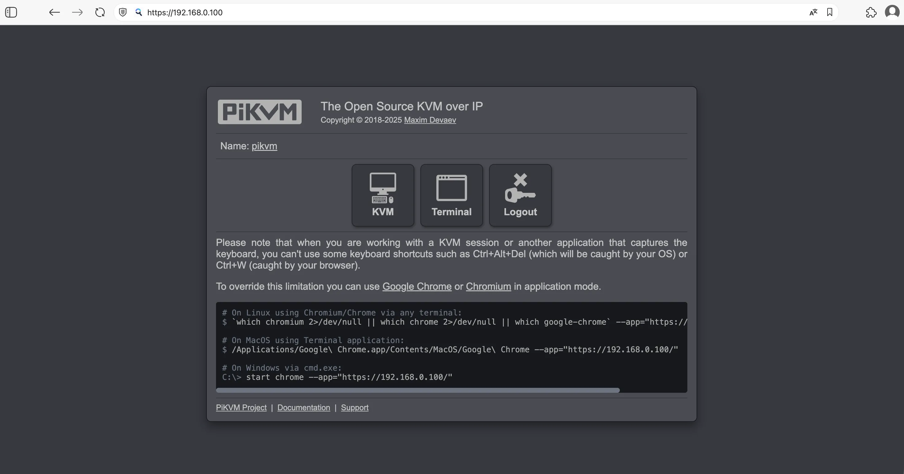
And there you go! PiKVM is installed, congratulations! You can now see the home page with three main buttons:
- KVM: to access your server
- Terminal: to access the PiKVM terminal and modify configurations
- Logout: to sign out
Note: If the page doesn’t load, check that your browser is allowed to access the local network. Some browsers block this setting by default.
Accessing the Server
To access the server remotely, just click the KVM button on the home page. You’ll be redirected to the KVM page, which gives you access to your server as if you were sitting right in front of it.
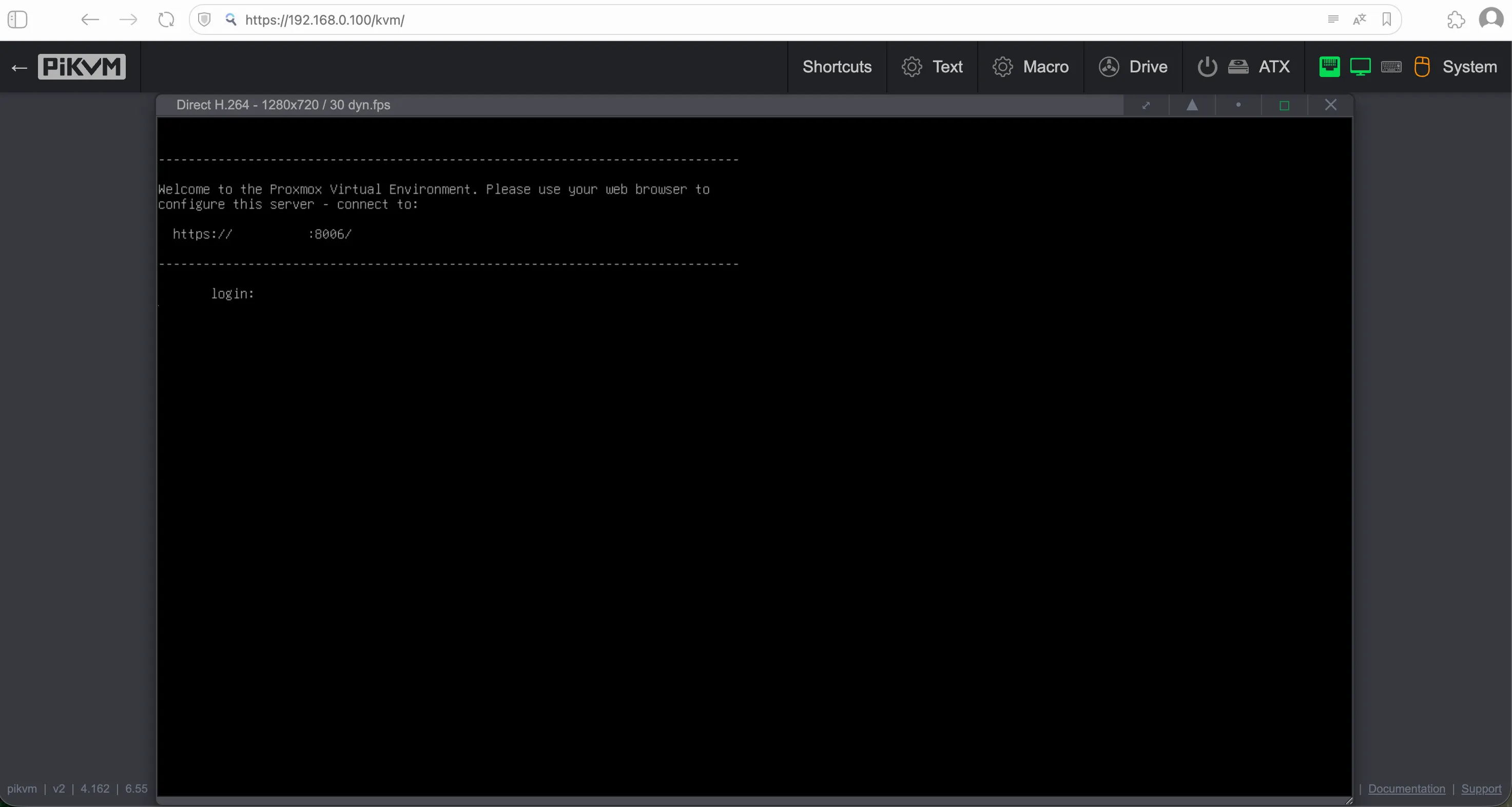
Note: If nothing appears on screen, it may be due to the video display mode. Try a different mode by clicking the “System” button in the top right and choosing one of the three Video mode options:
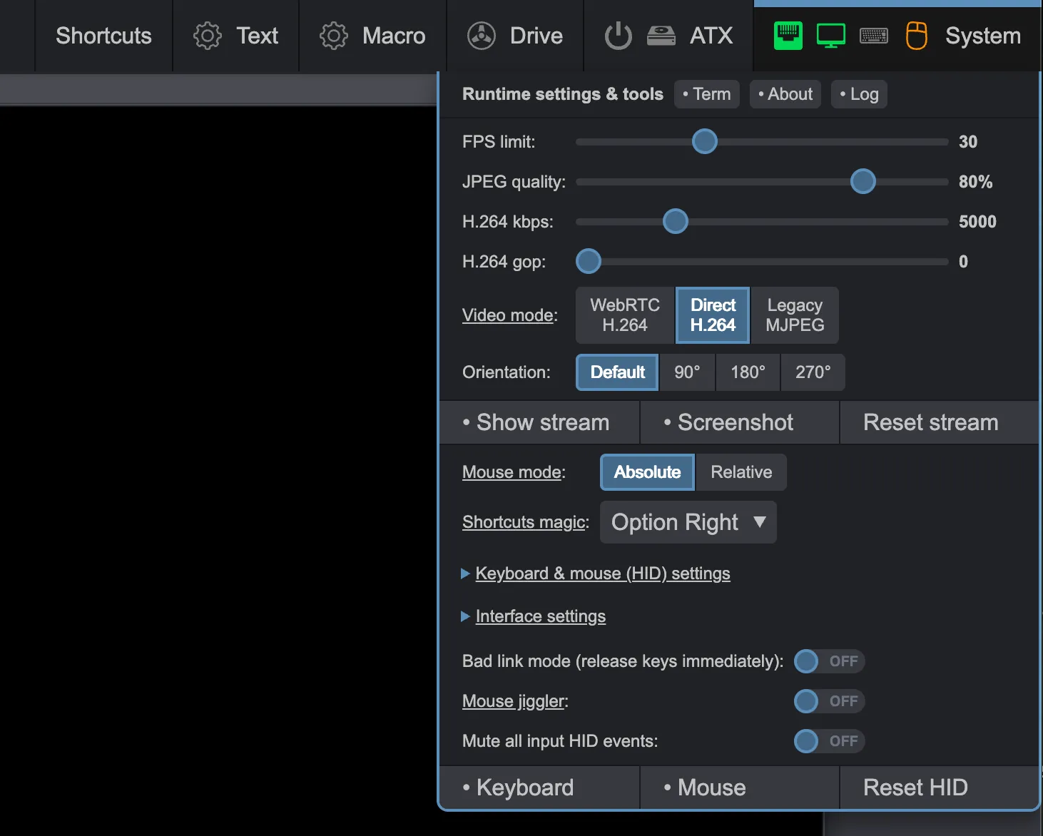
For more information on the various configuration options, refer to the documentation.
Accessing the PiKVM Terminal
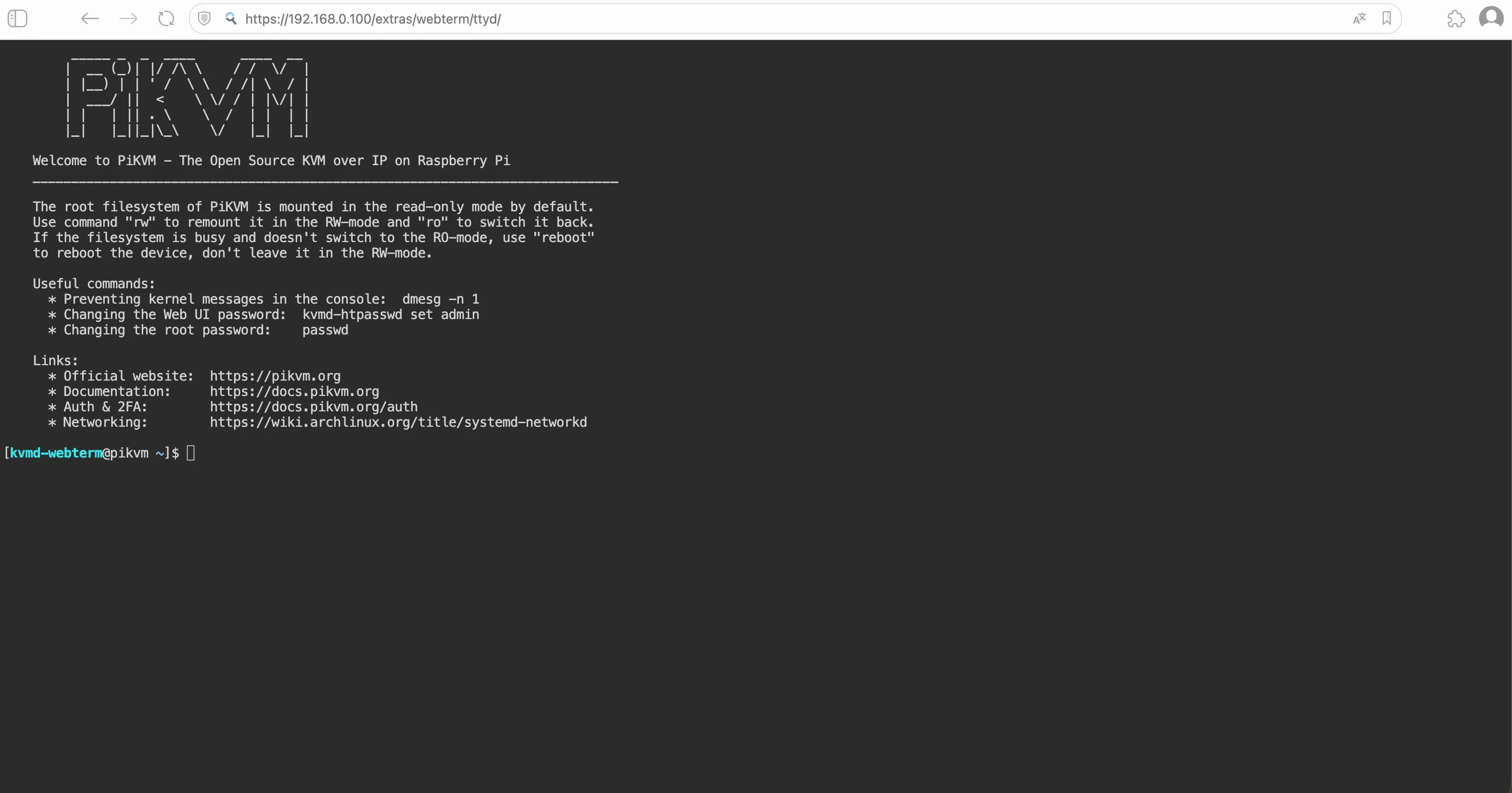
By clicking the “Terminal” button on the home page, you’ll get access to a Linux terminal where you can make all the necessary configurations. This is where you can secure your PiKVM by changing the default passwords and enabling two-factor authentication (2FA).
6. Securing PiKVM
Now that you have access to the web interface, it’s imperative to change the default credentials. Your PiKVM has full control over your server. If it’s not secured, that’s a wide-open door into your infrastructure.
The PiKVM system is based on Arch Linux and runs in read-only mode by default. For any modification, you’ll need to switch to read-write mode.
Changing Passwords
To change the Linux superuser password and the web interface password, you must be the root user and switch to read-write mode. Below are the steps to follow per the documentation.
- Switch to root user with the
su -command:
[kvmd-webterm@pikvm ~]$ su -
Password:
[root@pikvm ~]#
The default password for the root account is root.
- Switch to read-write mode with the
rwcommand:
[root@pikvm ~]# rw
+ mount -o remount,rw /
+ mount -o remount,rw /boot
+ set +x
=== PiKVM is in Read-Write mode ===- Change the root password:
[root@pikvm ~]# passwd rootThe password must be entered twice for confirmation. If you see the message passwd: password updated successfully, the password was changed successfully.
- Change the web interface password:
[root@pikvm ~]# kvmd-htpasswd set adminAs with the root password, enter the password twice for confirmation.
- Once the changes are done, switch back to read-only with the
rocommand:
[root@pikvm ~]# ro- Exit root mode with Ctrl+D or by typing
exit
[root@pikvm ~]# exit
logout
[kvmd-webterm@pikvm ~]$
Enabling Two-Factor Authentication (2FA)
This is an essential security layer. PiKVM makes TOTP setup very easy (compatible with all OTP apps like Proton Authenticator or 2FAS). To configure two-factor authentication, it’s straightforward (still as root) following the documentation:
[root@pikvm ~]# rw
[root@pikvm ~]# kvmd-totp init
[root@pikvm ~]# ro
Once you run the kvmd-totp init command, it will display a QR code you can scan with your OTP app.
Warning! Make sure NTP is configured correctly and the time is accurate. You can check this with the timedatectl command:
[root@pikvm ~]# timedatectl
               Local time: Sun 2026-04-12 21:47:33 CEST
           Universal time: Sun 2026-04-12 19:47:33 UTC
                 RTC time: n/a
                Time zone: Europe/Paris (CEST, +0200)
System clock synchronized: yes
              NTP service: active
          RTC in local TZ: no
The Time zone doesn’t matter, but verify that Local time is correct. Otherwise, head to the next section to configure NTP.
If you need to display the QR code again, use the kvmd-totp show command.
If you need to remove 2FA, use the kvmd-totp del command.
⚠️ Warning: Never expose PiKVM directly to the Internet!
PiKVM gives full access to the server, including the BIOS. If you need to access it from outside your local network, you must use:
- A VPN like WireGuard, OpenVPN, or Tailscale.
- Or a reverse proxy (Nginx, Caddy, Traefik) with strong authentication (e.g. basic auth + 2FA) and a TLS certificate (like Let’s Encrypt).
Avoid simple port forwarding on your home router, as it exposes PiKVM to brute-force attacks or exploits.
7. NTP Configuration (via chrony) and Updates
Now that security is in place, let’s focus on time synchronization. A well-synchronized clock is essential for two reasons: ensuring 2FA works correctly (a drift of a few seconds is enough to invalidate TOTP codes), and accurately measuring WebRTC latency between PiKVM and your browser. This measurement relies on comparing the clocks of both machines, which must be synchronized. Following the official latency documentation, we’ll use chrony.
Updating and Installing chrony
Before installing anything, let’s start by updating the package database and the system.
[root@pikvm ~]# rw
[root@pikvm ~]# pacman -Syy
Next, install chrony:
[root@pikvm ~]# pacman -S chronyBefore starting chrony, you can modify its configuration to, for example, use different NTP servers. That’s what I did to use my internal local NTP server in my homelab. This way I synchronize all my servers together.
The chrony configuration file is at /etc/chrony.conf:
# /etc/chrony.conf
# Welcome to the chrony configuration file.

# Use only the local NTP server - CHANGE THIS
server 192.168.0.10 iburst

# File to store clock drift information
driftfile /var/lib/chrony/chrony.drift

# Directory to save NTS keys (if used)
ntsdumpdir /var/lib/chrony

# Avoid abrupt clock adjustments
maxupdateskew 100.0

# Sync the hardware clock (RTC) with the system clock
rtcsync

# Step immediately if offset exceeds 1 second (first 3 updates only)
makestep 1 3

# Use TAI-UTC offset information from the timezone database
leapsectz right/UTC

# Log directory (optional, uncomment if needed)
logdir /var/log/chrony
# log tracking measurements statistics
In the chrony configuration above, I hardcode the IP of my NTP server (server 192.168.0.10 iburst). You’ll obviously need to change this to match your NTP server, or keep the default configuration.
I also recommend updating the timezone:
[root@pikvm ~]# timedatectl set-timezone Europe/ParisFinally, stop the old NTP service and enable chrony:
[root@pikvm ~]# systemctl stop systemd-timesyncd
[root@pikvm ~]# systemctl start chronyd
[root@pikvm ~]# systemctl enable chronyd
Once done, lock the system and reboot to verify everything starts correctly at boot:
[root@pikvm ~]# ro
[root@pikvm ~]# reboot
To keep PiKVM secure and performant, remember to regularly update the system and packages with the pacman -Syu command (as root in rw mode).
8. Conclusion
Congratulations! You’ve turned a small Raspberry Pi Zero 2 W into a professional-grade administration tool.
For about fifty euros, you’ve just gained:
- Remote BIOS access
- A keyboard/mouse console accessible anywhere on your network
- Peace of mind every time your physical server crashes
It’s a time investment you won’t regret the next time your Proxmox server decides to act up on a Sunday evening. No more fetching a keyboard and monitor (or the TV screen), everything now happens in your browser!
What’s Next?
If you want to go even further, PiKVM can also manage your server’s physical power (Power On/Reset) via GPIO pins, or even monitor temperatures. But for today, you already have the essentials to take back control.
The next step for me is building a nice case for my PiKVM once I get my hands on a 3D printer, because for now it’s a bit of a mess sitting on top of my server.
Thanks for reading this article, and feel free to send me feedback if you have questions or suggestions to improve it!